Your cart is currently empty!
The Boombox
Developer:
Caliber:
Type:
Platform:
Date Published:
Difficulty
/ 10
Pew’s Summary
Project Documentation
Build Guides
More From this dude
About This dude
Build Guides and Tutorials
More from this dev
Coming Soon
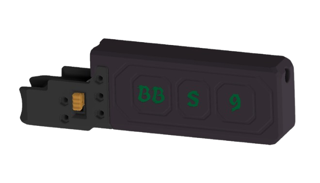
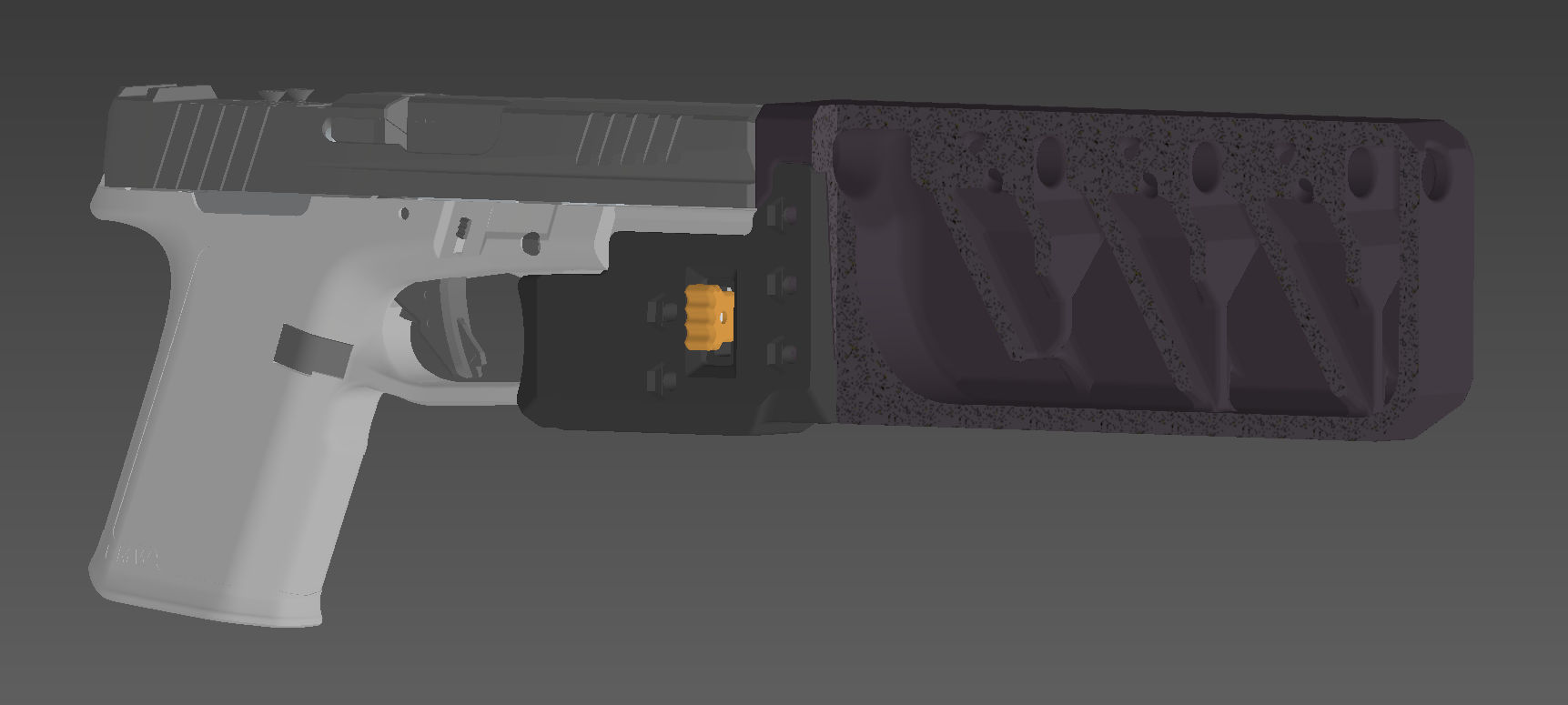
# BOOMBOX
Rail mounted muzzle devices
Rail mounted muzzle devices
by ToxicXzombieG
## Description
The Boombox is a rail-mounted muzzle device available in multiple configurations,
including Suppressor, Compensator, Flash Suppressor, and Threaded Barrel (TB) options.
The files are separated into mounts and cores. Various mounts are available to suit different
firearms, or you can create your own. The core, which serves as the muzzle device of your choice,
is bolted onto the mount. Note that this is not the most effective suppressor, as it lacks a seal
for gases, but it still performs better than having no suppressor.
!!!WARNING!!!: This can damage your frame, especially if it's printed.
There is only 1 OEM frame that's been damaged in testing; it was a Walther PPS.
The Walther PPS has a very small rail and its very thin polymer, making it not suited for this.
If your printed frame isn't strong enough, it may break part of the rail off.
The mounts included in this release have not had this issue.
There have not been any issues with Picatinny and Glock rail-based mounts reported.
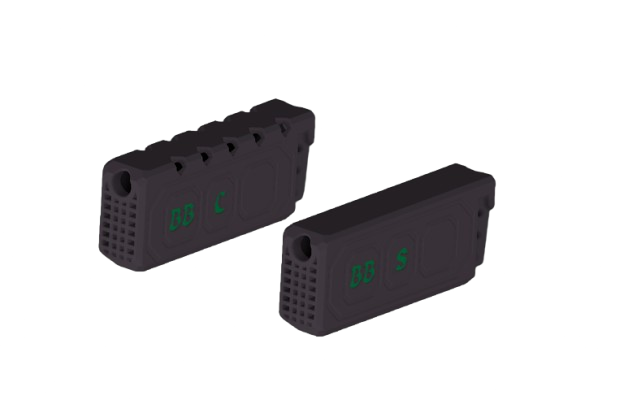
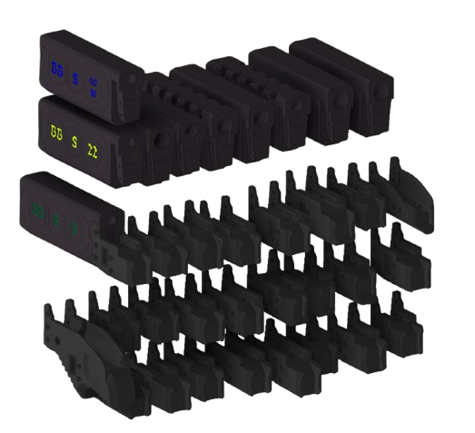
## Variants
– **CORES** – suppressor cores in 22, 9mm, .40/10mm, 45. multicaliber compensator and flash suppressor cores
– **TB CORES** – all the same cores but with room for a threaded barrel to sit in and tilt
– **MOUNTS** – mounts for various frames tested ones are here for beta mounts check my odysee page
## Materials Required
Printed parts
1x Mount
1x Core
1x Locking Bar
2x Grips
2x Printed Pins
1x thread protector – optional
1x tpu o-ring ——— optional
Purchased parts
5x M4x35mm Countersunk Bolts
1x M4x50mm Countersunk Bolt for rigid mount
5x M4 Nuts 6 needed if using rigid mount
1x Spring (8mm OD, 30mm length, 0.8mm wire diameter)*
*Note: Ender bed springs will also work.
The spring does not need to be exact, but it must be no larger than 9.5mm OD and at least 25mm long to fit and function properly.
It should apply enough force to lock the mechanism.
Insufficient locking pressure may cause the spring to compress, leading to the core and mount detaching or breaking.
If this occurs, use a longer or stiffer spring.
Excessive spring tension will not cause harm but may make installation and removal of the mount more difficult.
Reinforcement Options
3M casting tape 82003A (adding additional epoxy increases strength)
Fiberglass or carbon fiber with epoxy
Optional Components
A thread protector and TPU O-ring are available for threaded barrels to help seal gases while allowing the barrel to tilt.
The TPU O-ring, compatible with 95A TPU, melts quickly, so printing multiple spares is recommended.
The thread protector should be printed using a high heat-resistant material, with PLA Pro/Plus as the minimum viable option.
## Instructions
Print settings
These settings significantly improve layer adhesion and are strongly recommended for optimal results.
.4mm nozzle .6mm nozzle 12 walls
.16mm layer height .24mm layer height 9 top and bottom layers
.52mm inner wall, infill line widths .8mm inner wall, infill line widths 99% infill
*60mm/s *30mm/s
Print at the maximum temperature your filament can withstand, as higher temperatures
improve layer adhesion. If using a hardened steel nozzle, which conducts heat less
efficiently than other materials, consider increasing the temperature by 10–20°C.
VOLUMETRIC FLOW 6mm³/s
In Orca, Bambu, Prusa, and Creality slicers, a filament-specific volumetric flow rate
limit (in mm³/s) can be set to automatically regulate print speeds. To access this setting,
enable the advanced settings option. Then, navigate to the filament settings, and locate the
volumetric flow rate (or speed) setting at the bottom of the filament tab.
*If your slicer does not include the volumetric flow rate option, set the print speed to a maximum for your nozzle size.
PRINTING
The cores should be printed on the left 45° face. All STLs are pre-oriented in the slicer.
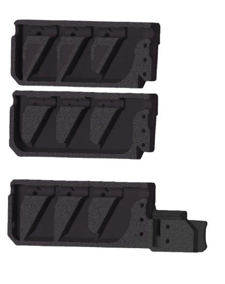
For the mounts I included a flat cut mount and an uncut one.
If you want to use the uncut mount follow the advanced instructions.
Standard
Use the flat cut mount.
Advanced
The mount must be cut in half (17.5mm) in the slicer. Optionally you can add connectors.
Each mount is different, so you will need to determine the placement of the connectors.
An example is shown in the pictures in the pdf. Once the mount is cut, lay both halves with the cut side facing up.
SUPPORTS
The mount should not require supports if cut.
The grips, locking bar, and pins do not need supports.
The cores will require supports.
REINFORCEMENT
Reinforcement is recommended, but it will also work without.
Bare PLA lasted roughly 50 rounds of 9mm rapid fire with no reinforcement.
3M tape-wrapped PLA survived over 100 rounds of rapid fire with no breaks.
Unreinforced PLA doesn't work for everyone; it is highly dependent on layer adhesion.
To ensure durability, wrap it.
Alignment Testing
It is recommended to check the alignment of the barrel and cores before use.
Included in the files are alignment test cores and rods.
The test core is available in both threaded barrel and non-threaded barrel versions, consistent with other cores.
To test alignment:
1. Attach the test core to the mount you plan to use.
2. Insert the appropriate caliber test rod into the barrel.
3. Slide the mount with the test core onto the firearm and confirm it is securely locked.
4. If the rod passes through the core without touching it, the alignment is correct. If not, the mount will require adjustments
Assembly
Assembly and reinforcement video found here https://odysee.com/@ToxicXzombieG:3/BOOMBOX-ASSEMBLY:c
You will need the bolts, nuts, spring, any core, any mount, two printed pins, two grips, and the locking bar.
1. Bolt the mount together with the holes behind the locking bar.
2. insert the spring into the hole.
3. Use the locking bar to compress the spring while sliding it into place.
4. put the grip onto one side of the locking bar. the small cutout on the bottom (highlighted in pink) facing away from the core.
5. Insert the printed pin through the grip and bar, then hammer it until it sits between the two ridges on the pin (highlighted in blue).
6. Snip off the excess pin; it should be flush with the grip.
7. Repeat steps 4, 5, and 6 for the other side.
8. Slide the core in and bolt it together.
REINFORCEMENT
Reinforcement is recommended for all cores, but it can work without if you can print strong enough.
Bare PLA lasted roughly 50 rounds of 9mm rapid fire with no reinforcement.
3M tape-wrapped PLA survived over 100 rounds of rapid fire with no breaks.
Unreinforced PLA doesn't work for everyone; it is highly dependent on layer adhesion.
To ensure durability, wrap it.
3M CASTING TAPE WRAPPING
The casting tape is a fiberglass tape with water-activated resin.
It comes rolled up in small packs. For the Boombox, you can use one full roll per core.
Begin at the angled face under the bore and tightly wrap the entire core with about a 1.5-inch overlap with each wrap.
When you reach the mount side, start wrapping back to the end.
Continue this process until you run out. To activate the resin, run the wrapped core under water.
For an even stronger reinforcement, you can apply epoxy:
coat the outside of the core with epoxy, then apply the tape.
While wrapping, add more epoxy until run out of tape.
The 3M tape will take at least 24 hours to fully cure.
With epoxy added, it will take 48–72 hours to cure completely.
After wrapping, cut any excess where the core interfaces with the mount
and for the compensator and flash suppressor, you must cut out the ports on the front and top to allow the gas to exit.
For video of the boombox watch the assembly and reinforcement video found here
https://odysee.com/@ToxicXzombieG:3/BOOMBOX-ASSEMBLY:c
These are videos for the FTN suppressors, but the same process is used.
https://odysee.com/@Plaboi:2/strongest3M:4
https://odysee.com/@Plaboi:2/My-Movie-51:3
## Change Log
– v1.0: Version 1 Release
## License
NO IMAGES, INSTRUCTIONS, DOCUMENTS, NOR ANY OTHER FILES LICENSED FOR COMMERCIAL USE, SUBSCRIPTION DOWNLOAD, OR ANY PAID DISTRIBUTION WHATSOEVER.
COPYRIGHT 2025
Comments
Subscribe
We are consistently silenced by social media outlets and misrepresented in the press. Get the whole story, stay in touch with us, and stay up to

Post Categories
- Announcment (88)
- Bounty (9)
- Closed Bounty (1)
- Open Bounty (8)
- Developers (20)
- File Drops (179)
- Accessories (29)
- Comical Creations (2)
- Guides (3)
- Hybrid (10)
- Magazine (13)
- Primarilly Printed (9)
- Printable Frames (106)
- Suppressor (8)
- Files by Type (12)
- The Blog (109)
- Betas (52)
- In Beta (52)
- CTRLPew (8)
- Guides and Tutorials (21)
- News (29)
- YZY_Prints (1)
- Betas (52)
- Uncategorized (4)
")

Leave a Reply
You must be logged in to post a comment.